

Computer Aided Design (CAD) and Automation
By Sunny K. Tuladhar via Medium - This article tries to explain why CAD automation is needed ,how its done and why Mechanical engineers or CAD users in general, need to get acquainted with programming.
When we talk about Mechanical Engineering, CAD(Computer Aided Design) is something we associate with design and creativity and thus do not consider it a process that be automated.
This article tries to explain why CAD automation is needed ,how its done and why Mechanical engineers or CAD users in general, need to get acquainted with programming.
We associate CAD with modeling and designing complex products with regards to minute details that a customer might require, using simulations to test the design ,make changes and finally using the best design to actually manufacture the product.
We associate CAD with custom made designs, designs that have been specifically tailored for that specific product.
How then, can such a practice be automated and WHY should it be automated? (Some people might link automation with AI or Machine Learning, that is not what we are talking about for now. )
The answer to “CAN it be automated?” is obviously “yes”(this article wouldn’t exist otherwise), using software APIs and code. What is an API? It stands for Application Programming Interface. Here’s a short description.
“….. an API lists a bunch of operations that developers can use, along with a description of what they do. The developer doesn’t necessarily need to know how, for example, an operating system builds and presents a “Save As” dialog box. They just need to know that it’s available for use in their app.” https://www.howtogeek.com/343877/what-is-an-api/
(Basically ,for CAD it could be a function in the code that inputs a face of the model and returns whether it is a “Cylinder, Sphere , Conical, Flat” Surface. We don’t know how it is done and we don’t need to know. We are concerned with the inputs and outputs of the API. )
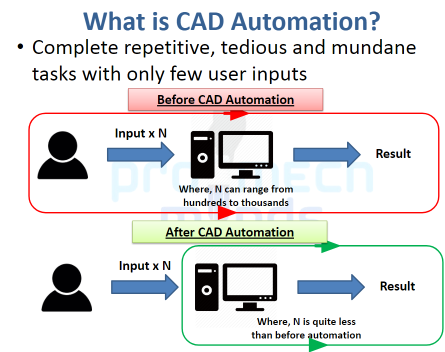
Design is a long and intense process and not all of the included tasks involve creativity. Most are repetitive and can be easily automated. The key is to automate these tasks to save more time for the creative processes.
E.g. Modeling of gears. Gears are mostly a standard part so having to model them every time is tedious. You can make an app to auto-generate the gear of required dimensions.
Taking the above image as an example. The number of input to make a gear from scratch (using sketches, extrude etc.) would a take lot more time than to just input its parameters(dimensions and getting the result). See another image below for the OnShape parametric gear tool.
The answer to “WHY we need automation?” is: to save time. A lot of time can be saved using automation. This saved time can be used by the designer to focus on more person-oriented decisions and creativity.
To understand CAD automation it helps to have a basic knowledge of coding and how computer algorithms work. CAD Automation goes hand in hand with Customization as most companies have extremely specific repetitive tasks that are often simplified by Custom Tools on that software.
Here are a few examples of CAD Automation.
Parametric Modeling: One of the things you have to understand is a product is made from the assembly of many parts and most of these parts are standard parts (as opposed to custom parts) and to be able to generate these standard parts instantly without having to actually model them saves a lot of time. This is called Parametric Modeling. In this you only have to enter a select number of dimensions of a part and you get an output model of the specified dimensions. The software generates the model directly based on the dimensions only.
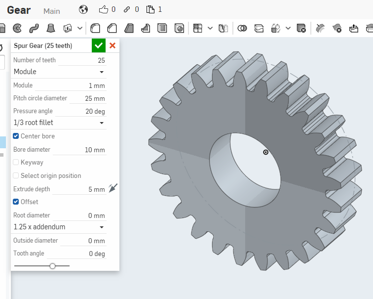
For Example : Suppose you need a standard spur gear for your product. In the above image, you have to enter the required dimensions(The Parameters) i.e. Number of teeth, Module, Pitch circle diameter etc. and the required gear model will be automatically generated.
Custom CAD Tools: All companies have their own share of repetitive tasks. Each has its own requirements. If a tool can be created for that specific task in the software that is to be used then it reduces the job time from days to hours and even minutes. Now almost all CAD software have a certain degree of customizing ability in them. Using their APIs you can create tools to automate extremely specific tasks.
OnShape has built its own language called FeatureScript which is designed specific for CAD users with no previous knowledge of programming. The actual features(Tools) in the Software are made using this script so you can copy the codes from the original tools and use it in your custom tool. The above mentioned Gear Tool is also a custom tool made using FeatureScript.
More on FeatureScript : https://cad.onshape.com/FsDoc/
Here is the FeatureScript code for the above mentioned Gear Tool. https://cad.onshape.com/documents/5742c8cde4b06c68b362d748/v/d9a567ca70312617baeb64e8/e/01a666571e625f8b819fd75b
Other softwares also have built their API in the required languages. For example Solidworks has its API in VBA, VB.NET, Visual C#, Visual C++ 6.0, or Visual C++/CLI.
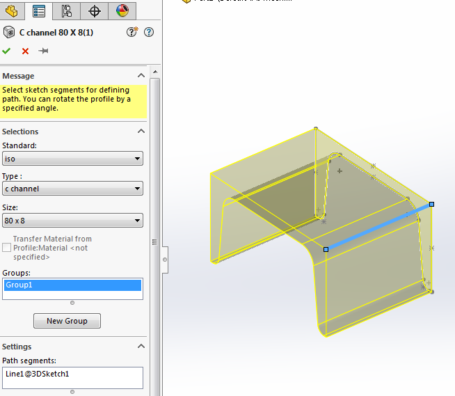
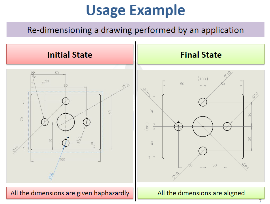
The image shown above is the dimension arranger tool developed by Shashank Dewan for SolidWorks. It arranges haphazard dimensions into a clean looking non-intersecting dimensions drawing. This simple tool saves time as the drafter can just give dimensions randomly for confirmation and the API will automatically create the clean presentable version.

Feature Recognition: Suppose you want to search for an available standard part based on a part you just modeled or for you assembly. Previously, you would have to go to a company website and search for the part based on serial numbers and part names. Now it is possible to input a 3D model of the part you modeled and get a list of recommended parts based on your 3D model. Of course this has not been implemented in all websites but this is a lot easier than the previous process. This is all possible due to Feature Recognition.
Feature Recognition in 3D CAD, is basically a software’s ability to distinguish shapes and tell what the 3D model is. It basically works by knowing this circular shaped thing is a “Cylinder”. By combining basic shapes (cylinders, cuboids, holes) a software can be made to correctly classify parts to a given list of part types. E.g. a Bearing, Screw, plate , Shaft
Another use for Feature Recognition is to evaluate, measure dimensions of a part. This is particularly useful when you have to model tens of thousands of parts and have to confirm(check) the dimensions of each. If a person takes 5 minutes to check the dimensions, the computer can do it within 3 seconds. Multiply that by 10000 and you can imagine why Automation saves time.
In conclusion, automation in CAD has really changed the way we approach design and manufacturing. It has simplified tasks that would have been extremely tedious and time-consuming to do manually. At the same time it has created a small black-box of mystery of how the tasks in the software are actual performed. So for CAD users today it really helps to have a basic understanding of programming and computer algorithms to understand how a software works. Once we can do that it becomes easier to understand what can be automated and how it can be automated and hence make our lives easier.
P.S. A personal anecdote:
Working as a CAD Engineer there were times when we were asked by a Japan-based company to rename files. As mundane as the task it may sound, all CAD engineers must have experienced this. When old part drawings and models are reused for other products the file names have to be changed.
For example: When a parts of PSG 666 are going to be used for PSG 648 then file names PSG -666- 001.cad ,PSG -666- 002.cad…. will have to be turned to PSG-648 -001.cad , PSG -666- 002.cad…. There were 600 files to be renamed!!
There were many methods using Python or C# code to rename all the files at once, but that would need installing the language in the PC. Since the PCs are licensed you cannot install any extra programs. Fortunately I discovered a batch file code that could be used to rename multiple files at once.
The script file shown below runs by default on windows and does not require any extra installations. I used this code and the job that would have required 1 hour was finished in 2 seconds.
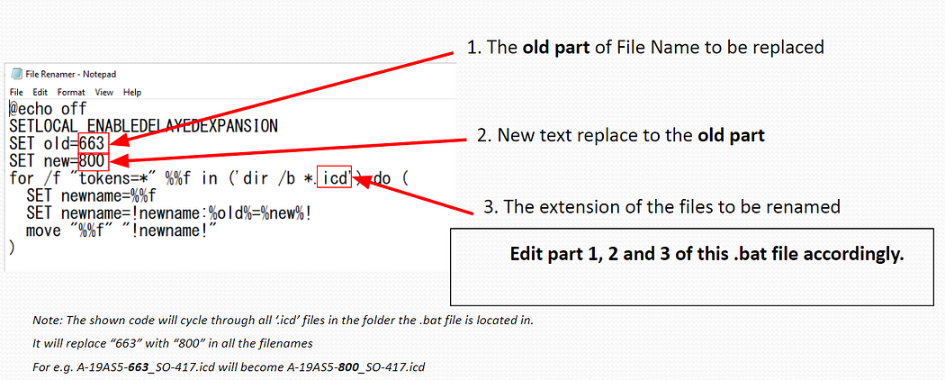
This is a very simple and not a direct example of a CAD automation but still you get the basic idea. If you think a task can be automated, it is always worth it to find out how it can be done. Automation saves time, use it!

