Taking It to the Next Level: Drawing Automation with Autodesk Inventor
Learn the basic techniques of developing the logic required to automate 2D drawings with iLogic and the Inventor API.
We’ve all heard it before: “You can’t automate drawings with iLogic.” Well, we’re here to tell you that you can! With this article, you’ll learn the basic techniques of developing the logic required to automate 2D drawings with iLogic and the Inventor API. You’ll learn about creating views, adding dimensions and balloons, and working with sketched symbols and even parts lists. This information will shed an abundant amount of light on how to develop your drawing automation, as well as what to avoid, ensuring a robust and stable automation project.
Taking properly developed and designed 3D models, generating drawing views, adding dimensions and balloons, updating parts lists, adding and manipulating sketched symbols: this is the arena where Inventor Automation can do a lot of work and be ultimately beneficial. But this little gem is hard to come by. It takes time to plan, prepare, and process all the requirements to implement a project of that nature. But fear not, it can be done.
The Four Key Aspects of Inventor Automation
Let me begin by saying that any successful Inventor Automation project will require a plan. A plan will require knowledge and intelligence, the kind of intelligence that provides status and the current state of affairs. You must be intimately familiar with your data or surround yourself with the right team of people that are. You must know where you’re starting from before you can determine how to get to where you want to be.
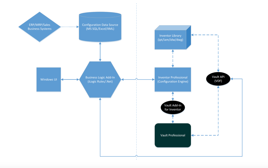
Autodesk Inventor Automation Data Flow
- Logic
- Model Development
- External Data Sources
- User Interface
Overview
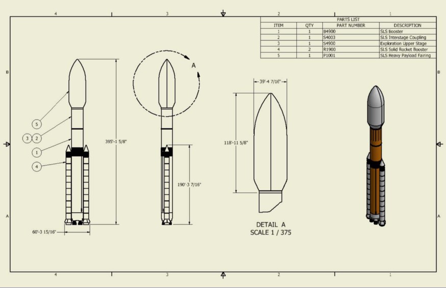
One of the steps within design processes companies ask me about on a frequent basis is Model Configuration. In the past, I had created a couple demonstration datasets that displayed some of the out-of-the-box features of iLogic and how anyone can build a rudimentary Product Configurator. It’s important to be able to take a pool or collection of part and assembly models and put them together in an accurate and consistent manner, obeying best modeling and assembling practices ensuring the stability and integrity of the 3D information. This is definitely an area in the development process where everyone can relate.
This article will demonstrate the process of using a developed model configuration to “automatically” generate the 2D design documentation used for quoting, fabrication, or manufacturing. Topics of discussion will focus on the essential features needed to develop 2D drawings, to include:
- Creating, naming, and activating Sheets
- Defining the model reference
- Creating, naming, locating, and scaling Views
- Creating and modifying Parts Lists
- Adding Dimensions
- Placing Balloons
- Adding and locating Sketched Symbols
- Working with iProperties and Parameters for Title Blocks
Planning
For any automation project to be successful, you must plan. Having a plan, with objectives to monitor and manage success metrics, will allow for contingencies to be accounted for, as well as having some type of road map to follow for the design. How many Sheets are needed for the Views and Dimensions needed to capture a design? What notes need to be included? Do the notes vary depending on the type of design needing to be documented? Do we know enough to predict how the drawings need to be configured? Does a user need to interact with the process? There are many questions that you must ask yourself, a plan will help you understand what those questions are.
Drawing Automation is a departure from Model Automation. In my previous AU classes, I have discussed how to develop Product Configurators, taking models and putting them together in specific configurations to represent what it is you produce or manufacture. 3D models are engineering “gold” when it comes to conceptualizing and visualizing how to put something together. It is, without a doubt, essential in performing analysis, reducing costly prototype creation, and expediting roll-out time from concept to production. But having the detailed drawings of those configurations is where most of us find the value. Without the drawings, humans have a challenging time manufacturing anything with quality and consistency. Imagine building a house without blueprints! Good luck.
To pull off a Drawing Automation project in Inventor requires understanding of how Inventor works. Remember, iLogic does not change how Inventor works, it only changes how you work Inventor. Without knowing that a View requires a reference, or Dimensions need two points selected, or anything of the sort, it will be extremely difficult to understand what is required to automate the process. Also, Drawing References are Models, don’t forget to give those Models some special attention. Look for the Model Development section below to understand how to prepare those valuable 3D models.
Related: Inventor iLogic Best Practices and Fundamentals for Success with Thomas Fitzgerald
Logic
Where Do I Start?
I’ll admit, I’m not a programmer. I’ve never taken a class, I’ve never gone to school to write code, I didn’t have a Yoda to seek advice from, unless you consider Google a Yoda-like figure. The Internet has a wealth of information available to do certain little steps with whatever code language you would like to learn. I started learning Visual Basic .Net a while ago because of the need to understand iLogic. But, depending on your Inventor Automation architecture, you can use C# .Net as the code language for the logic, but the first step is to understand what language you want to use.
To iLogic or Not to iLogic?
I get this question all the time. “Which is better, iLogic or the Inventor API?” Honestly, they are one in the same. I’ve always considered iLogic like a door to the Inventor API. It’s just an environment with a library of commands that leverage the Inventor API to do Inventor tasks.
The key to deciding whether to use iLogic or not depends on several different factors. Do you want to accomplish simple little tasks like updating iProperty information? Or do you want to update Part Feature data or maybe even create a pseudo iAssembly, basically controlling the Suppression state of components within an assembly?
Another factor that should be taken into consideration is security. Because of its readily available tools and interface, most companies, when designing and developing their iLogic code, use the default settings and store their iLogic code within the files themselves. This presents a couple undesirable situations. First, the code is exposed to anyone that has access to the file, which in most instances, is fine. But one can spend a lot of time and effort putting together the code in such a way that other personnel should not be tinkering with it. Often, there could be sensitive information involved with the code that for obvious reasons, we don’t want out there and available to just anyone. External Rules can alleviate this problem to some degree by securing the Rule logic out on the network somewhere, and us the network security to prevent prying eyes from seeing exactly what is in the code.
If you’re looking to do a more complex series of tasks with your Inventor Automation, like connecting to other business systems, or if you need real-time updated database information, then I’m going to suggest using Visual Studio and the Inventor API. Creating an Inventor Add-In can provide you the security and single environment to do all your UI and Logic tasks needed for your automation project.
The Inventor API
API, or Application Programming Interface, is the recipe for “doing” in Inventor. If you want to draw a line in a sketch, you select the Line button and then you input what Inventor requires. First, you select a start-point, then you select an end-point. Each task in Inventor has a set of Functions to do everything from drawing lines, to creating assembly constraints, to scaling drawing views. Understanding the intricate steps of each task in Inventor is crucial for planning and implementing an automation project.
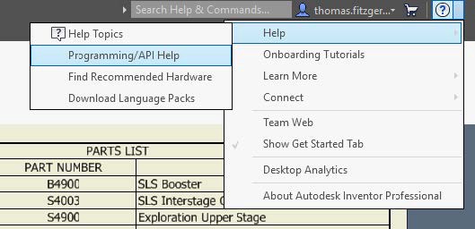
During the planning stage of your automation, outlining the Inventor steps from the perspective of the Inventor API will greatly expedite the logic development. Take for instance the concept of developing your drawing automation. One of the first steps when manually creating a drawing is defining what template to use, naming it, and then saving it. After that, how many Sheets are needed? Look in the Inventor API help to see the function to create a Sheet.
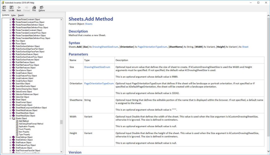
Now, I know it’s daunting. I was lost and confused the first dozen times I looked at it too. But, there is a lot of information out there on how to read and use the Inventor API. Look it up, do a search on YouTube, you’ll be surprised at the number of examples, tutorials, and videos available.
Code Structure and Organization
What’s the best way to structure your code? What I’ve learned through my experience is, the more generic, the better. Each Function, Subroutine, or Rule that you will create should be as simplistic and ambiguous as possible. Each one will have an input, the data that is required for the nature of the Function. Data mining, manipulation, and interpretation are most prevalent in this phase of the project.
Even if you intend to use iLogic as your logic tool, organize your Rules in such a way that they perform a specific function or task. You can call on those rules at any time from another rule to better control when your logic fires specific routines. It’s always better to have a lot of small rules then one large, complex rule. Your Functions and Subroutines should be written in the same manner.
Naming Convention
The ability to identify files to use in Inventor Automation is one of the key points to be aware of for Model Development. As an example, if you as an Inventor user decided that you wanted to add a component to an assembly, you need two bits of information; File Name and File Location. Some companies use what is called a “smart file naming convention” where each character in the File Name has some sort of meaning, typically followed by a sequential number to ensure uniqueness. Some companies use an arbitrary or random combination of alpha and numeric characters to name their files. Typically, these companies use a Document Management system like Autodesk Vault where database properties can be searched to identify files. Instead of relying on file names to be logical and have meaning, companies using a PDM can create search queries to find files based upon engineering or design information.
Whatever process you use to name files truly doesn’t matter. What is important to focus on is what the convention might be. Similarly, Drawing Automation may require Sheets, Views, Work Features, and Entities to be named to identify and access them for different logic processing. If you want to add a Dimension to a View, what View? Adding a Balloon to a component in an Assembly that is being referenced in a View? You might need to add an Attribute tag to a Face in the component. What’s the name of the Attribute you want to find? Giving them logical names makes this exercise much simpler.
Drawing Automation
What Is Drawing Automation?
What do we have to do to make sure drawings get created automatically? ‘Automatic’ is a word that is subject to interpretation. To most, it means that something happens without any human interaction. That would be in a perfect world. However, in engineering, we simply want to minimize the amount of human interaction, particularly if a process is repeatable, predictable, and relatively consistent. If we can automate the process, then we can ensure quality and consistency by removing the possibility for human error. It also allows us to utilize our staffing resources much more efficiently.
In Autodesk Inventor, Drawing Automation has specific steps to follow to accommodate the associations tasks have with one another. As in the example of generating a View, we first must identify a reference for that View. The next sections will discuss, in more detail, the process of developing your Drawing Automation.
Templates
Defining a template or series of templates to create your drawings from is the absolute first step in the process. You can use your default templates or create a whole new series of templates specific for the Drawing Automation. It doesn’t matter if you use the IDW or DWG file extension. Record the file path location of your templates, it will be necessary later.
Depending on the scale of your Drawing Automation, you may need many different templates. The template you use for one type of product may differ from another simply because the level of detail required. Creating a drawing of a single part file obviously would be different then a drawing of a complex assembly. Most of the time, you can accommodate a lot of these differences.
Sheets
After we identify what drawing template to use, next is Sheets. What number of Sheets do we need? What size do we need? What name do we want to apply to the Sheets? What about Borders and Title Blocks? The following items need to be considered:
- Naming Convention for your Sheets
- Sizing you Sheets, A size, B size, etc.
- Activating a specific Sheet
- Deleting Sheets
Views
Creating various Views allows us to capture the necessary geometric information to accurately define how something is configured. Inventor creates Views based upon Model Reference. We as end users can define which Model Reference to use for each View that is generated, depending on the type of View that is needed. The Inventor API allows us to define that Model Reference as well.
If you’re detailing a single Part file, well, the Model Reference would be consistent throughout the drawing. What about a complex assembly? There are many different components, subassemblies, orientations, visibility options, etc., that need to be taken into consideration. This is where understanding the power and strengths of Inventor will help you out. The following items need to be considered:
- Naming Convention for your Views
- What type of View is needed, Base, Projected, Section, etc.
- View Scaling
- View Positioning
- View Orientation
Use a powerful Naming Convention to identify Parts and Assemblies that need the Visibility turned off from within each View. There are methods to iterate through a View and turn off the Visibility of select components and subassemblies based on their name. Leverage Level of Detail Representations in your Assemblies to control what graphical information is present within the Views as well.
Tips
When working with Views, there are a few things that aren’t apparent when it comes to writing the logic code. First, Views are placed based on 2D points, essentially an X and Y. Second, View scale is difficult to judge. I always manage scaling based upon Sheet size. This way, no matter what Sheet size I use, the Views will always fit.
Parts Lists
For the most part, if you configure your Views correctly, the Parts List will take care of itself. But there are occasions where the Parts List does not reflect what you want to represent.
All of us at one point have created a View based on a Level of Detail, then placed a Parts List. Why do the components and subassemblies that I have suppressed still show up in the Parts List? Sometimes, we must filter components and subassemblies out because Level of Detail does not control the Parts List; View Representation filters do. We can also write code to do the same thing. We can also populate the Parts Lists with custom or “dynamic” information if we’d like. The following items need to be considered:
- Parts Lists location
- Content filtering
- Item renumbering
Dimensions
The topic of creating and placing dimensions in an automated fashion has challenged consultants like me for a while. An end user can simply look at a View and with the basic information, apply the dimensions needed to detail it out. But Automation cannot look at a View and process it visually. Code needs other criteria, other information to make determinations about how to place dimensions. A method I use applies Work Points to the components or subassemblies that graphically compose where my dimensions should go. After I create the Work Points, I rename them following a predetermined Naming Convention so when my code needs them, it can find them.
Depending on the type or category of file that needs 2D documentation, the number of Dimensions can be immense. Typically for a quote, you may just need overall dimensions, a footprint, connectivity information, etc. But for fabrication or manufacturing documentation, well, you can imagine. How do we easily control, manage, and consume the information needed to place all those Dimensions? As I discussed in my previous AU classes, I like to leverage External Data Sources for situations like this. Using Microsoft Excel or SQL databases allow for the flexibility and user friendliness needed to input and edit large amounts of data.
Tips
When working with Dimensions, there are a few things that aren’t apparent when it comes to writing the logic code. Dimension placement is based on 2D points, once again, X and Y. You need a start-point, an end-point, and a point for the text placement. Because the points are dependent on 3D graphical information, points need to be “projected” into 2D space. Get familiar with Geometry Intent in the Inventor API.
Balloons
When I first started using Inventor, I was amazed at the fact that if I pointed a Balloon at something else in a View, the Balloon number updated and reflected the corresponding item number in the Parts List. I was coming from AutoCAD, where quadruple checking the manual table we called a BOM to make sure item numbers matched was extremely tedious, time consuming, and prone to mistakes.
As I started working with Drawing Automation, I found that working with Balloons was much easier than I had anticipated. Identifying what needed a Balloon was as simple as Attribute tagging. In previous versions of Inventor, this was accomplished using a utility developed by Brian Ekins called Attribute Helper. It provides a simple, easy-to-use interface to select Faces, Edges, Points, etc., and apply a named tag to it. Then all you need to do is iterate through the files and find the Attribute, access its object, and viola, you now know what to attach a Balloon to. The hardest part of it all is placing the Balloon itself, ensuring you don’t interfere with other annotations in the drawing.
Tips
When working with Balloons, there are a few things that aren’t apparent when it comes to writing the logic. The Balloon placement can be controlled based on the attachment point or relative to the View. I find it easier to use the attachment point as reference and controlling the direction of the Balloon based on where the attachment point entity is. If the entity is right of the View centerline, then the direction of the Balloon is to the right. If it’s to the left, then left. You get the point. You can also control the Balloon shape type as well as the Balloon value.
Sketched Symbols
In Inventor, we control text blocks by using Sketched Symbols. They are predefined, stored within the drawing, easy to use, and can even be dynamic. They can even have Leaders to attach to geometry and move around. In my opinion, working with Sketched Symbols is the easiest of them all. You simply call the name of the symbol you want and define its location relative to the Sheet. Add Prompted Entry fields if you want to have dynamic Sketched Symbols.
Model Development
Attributes
Have you ever just wanted to give a Face or an Edge a name? Well, now you can! You have been able to for a long time now, but now we can do it easily. In Inventor 2019, if you select a Face or an Edge, and right click, you will see in the menu the opportunity to Assign Name. The name you provide will be the named Attribute to search for, as I explained when applying Balloons.
Another way to add Attributes, if you’re not using Inventor 2019, is by using the Attribute Helper.
The key to using Attributes for designating faces and edges is to have an adequate Naming Convention and understanding which files will be involved with the Balloon process as well as their orientation.
Work Points
I have found great success using Work Points to define where the start-point and end-point of any dimension is located. I create the appropriate Work Point in the necessary file, give it a logical name based upon a Naming Convention, and turn off the visibility. Because all dimensions have two points, I post-fix each corresponding Work Point with ‘1’ and ‘2.’ It allows for looping within the code much easier. I theorize that using Attributes to tag vertices will work, although I have not tried the workflow.
Finally
External Data Sources
As I mentioned before, External Data Sources can be extremely valuable, particularly if your Drawing Automation has aspects that include numerous variables. Microsoft Excel and Microsoft SQL Server are tools to use to accomplish storing and retrieving variable information, on demand. They also provide a user-friendly means of adding, updating, and administrating the design-specific information as your Drawing Automation scales and grows.
User Interface
Not all Drawing Automation projects will require a User Interface. Typically, a User Interface will be created and used when developing Design Automation, like a product configurator. If this is the case, the Drawing Automation will usually be an extension of the Design Automation and leverage its UI. However, a UI can be created to initiate the Drawing Automation process and provide a means to apply critical information to satisfy the inputs for the Drawing Automation.
Developing an Inventor Add-In
The next logical step in terms of complexity, level of effort, and functionality is developing an Inventor Add-In. Running iLogic rules by manually triggering them, or developing an iLogic form or forms, or creating windows forms in Visual Studio and using an iLogic rule to run them are very common ways of interfacing with your end users. But some companies have a need or desire to streamline how end users work in the Inventor environment. For those that want to go all out and truly “customize” Inventor, developing an Inventor Add-In is the way to go. My friend Brian Ekins has talked about this subject many times. Check out his AU class, Creating Add-Ins for Inventor.
Want to see some code examples? Download the full class handout.
Thomas Fitzgerald is a senior implementation consultant specializing in Inventor Automation and data management. Thomas has consulted with a large number of companies with a very diverse exposure to both large and small engineering departments. His work experience includes mechanical design within the automotive, shipbuilding, mining, and material handling industries as well as custom configuration applications utilizing the Inventor API, iLogic, Microsoft SQL Server, and Microsoft Visual Studio. Thomas has over 20 years of experience within the mechanical design and manufacturing industries using numerous Autodesk products. He is an Autodesk Certified Instructor as well as having his Microsoft Certified Systems Administrator credentials.